Interconnection Network Architecture
Message and Granularity
The fabric that interconnects multiple processors must have low latency and high bandwidth. The requirements of interconnection fabric performance stands for:
- messages are very short. Many messages are coherence protocol requests and responses not containing data, while some messages contain a small amount (cache-block size) of data
- messages are generated frequently, since each read or write miss potentially generates coherence messages involving several nodes
- message is generated due to a processor read or write event, the ability of the processor to hide the message communication delay is relatively low
Concept: Link and phit A link is a set of wires that connect two nodes. The minimum amount of data that can be transmitted in one cycle is called a phit. A phit is typically determined by the width of the link. The maximum rate at which a packet can be streamed through a link is referred to as the link bandwidth.
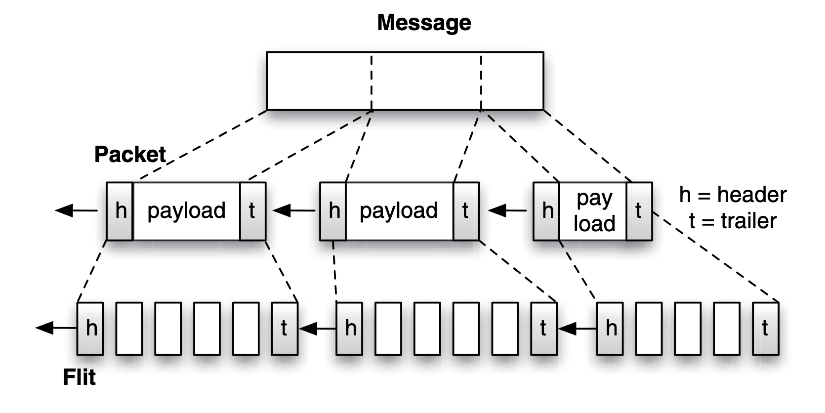
Concept: Packet Large message is fragmented and encapsulated into packets. Each part of the message becomes a packet payload, which is encapsulated by a header(h) and trailer(t). The fragmentation allows a message to be transmitted in parts independently of one another, and the header and trailer ensure reliable delivery of the message and contain sufficient information to reassemble the packets into the original message at the destination. If the packet header is designed to ft the size of a fit, the fit that contains the header is referred to as the header fit, the same for trailer fit. The packet payload is broken into body fits.
Link Level Flow Control
A fit worth of data can be accepted or rejected at the receiver, depending on the amount of buffering available at the receiver and the flow control protocol used. The flow control mechanism works at the link level to ensure that data is not accepted too fast that it overflows the buffer at the receiving router.
Lossy and lossless network:
- In a lossy network, overflowing a buffer results in fits being dropped and the dropped fits require retransmission in the future.
- For latency reasons, a lossless network is preferred, in which fits should not be dropped and retransmitted.
stop/go protocol A sender router sends fits of a packet to a receiver router as long as the receiver asserts a “go” signal:
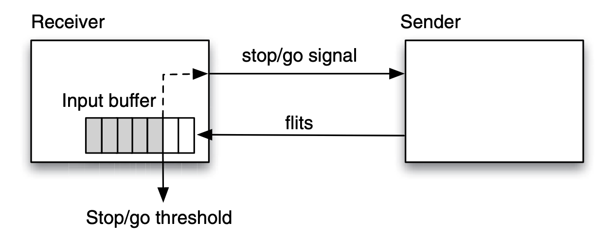
The stop/go threshold is determined by the round-trip latency between sender and receiver, such that there is no risk of overflowing the buffer.
credit-based protocol credit-based flow control requires the receiver to send out the precise number of entries available in its buffer. The sender uses this number to decide whether to send more fits or not.
Message Latency
Sending a single message of size over a channel in a network with bandwidth , is considered as the transfer as being composed of the latency of the first bit being transmitted to the destination (referred to as the header latency ), plus the latency for the remaining portion of the message trailing behind the first bit (referred to as the serialization latency ). Putting it together, the latency for sending the message is:
Where the first bit has to travel through hops and each hop incurs a routing latency of , then the header latency is , and the serialization latency is . Reducing the routing latency is difficult. However, the hop count can easily be increased or decreased by changing the overall topology of the network.
Network Topology
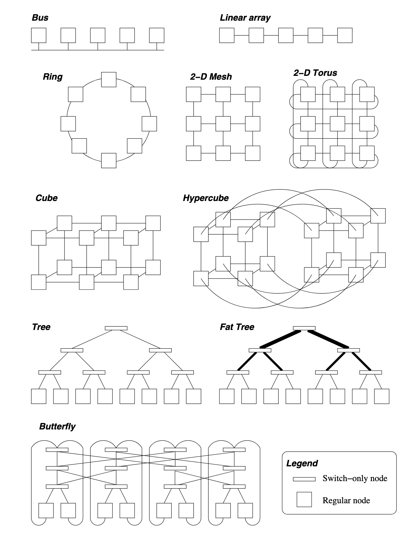
The k-ary d-mesh (a.k.a. k-ary n-dimensional mesh) topology is a typical one. For a k-ary d-mesh network, overall there are nodes in the system. The maximum distance in each dimension is one less than the number of nodes in a dimension, i.e., . Since there are dimensions, the diameter of a k-ary d-mesh is . The bisection bandwidth can be obtained by cutting the network into two equal halves. This cut is performed with a plane one dimension less than the mesh, therefore, the bisection bandwidth is .
Metrics of other topologies:
| Topology | Diameter | Bisection BW | #Links | Degree |
|---|---|---|---|---|
| Linear array | 1 | |||
| Ring | 2 | p | ||
| 2-D Mesh | ||||
| Hypercube | ||||
| k-ary d-mesh | ||||
| k-ary Tree | 1 | |||
| k-ary Fat Tree | ||||
| Butterfly |
Switching Policy
When considering that data will travel over more than just one link, there are two switching policies for a network:
- circuit switching, where a connection between a sender and receiver is reserved prior to data being sent over the connection.
- packet switching, when a large message is transmitted on a channel, it is fragmented and encapsulated into packets, the circuit may changes for each packet.
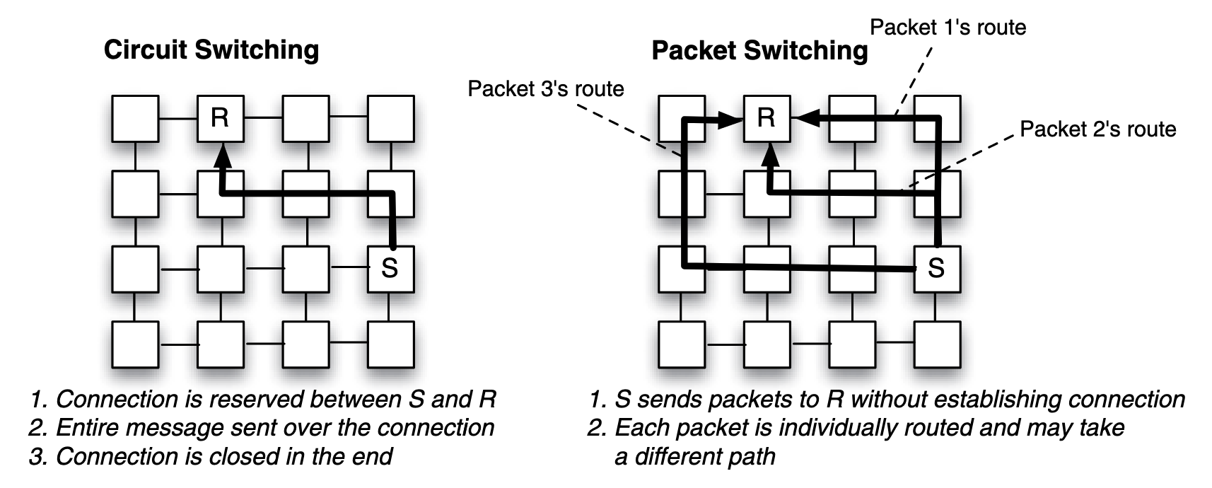
Comparing those two policies:
- Circuit switching requires a connection setup, which adds latency and risks underutilization if idle. Collisions delay other traffic until the connection is released. However, it offers fast message delivery, simpler routing, minimal buffering, and lower power consumption once established.
- Packet switching avoids setup delays, handles multiple traffic flows efficiently, but incurs higher routing delays, power consumption, and buffering needs at each router.
Routing Policy for Packet Switching
Store and Forward
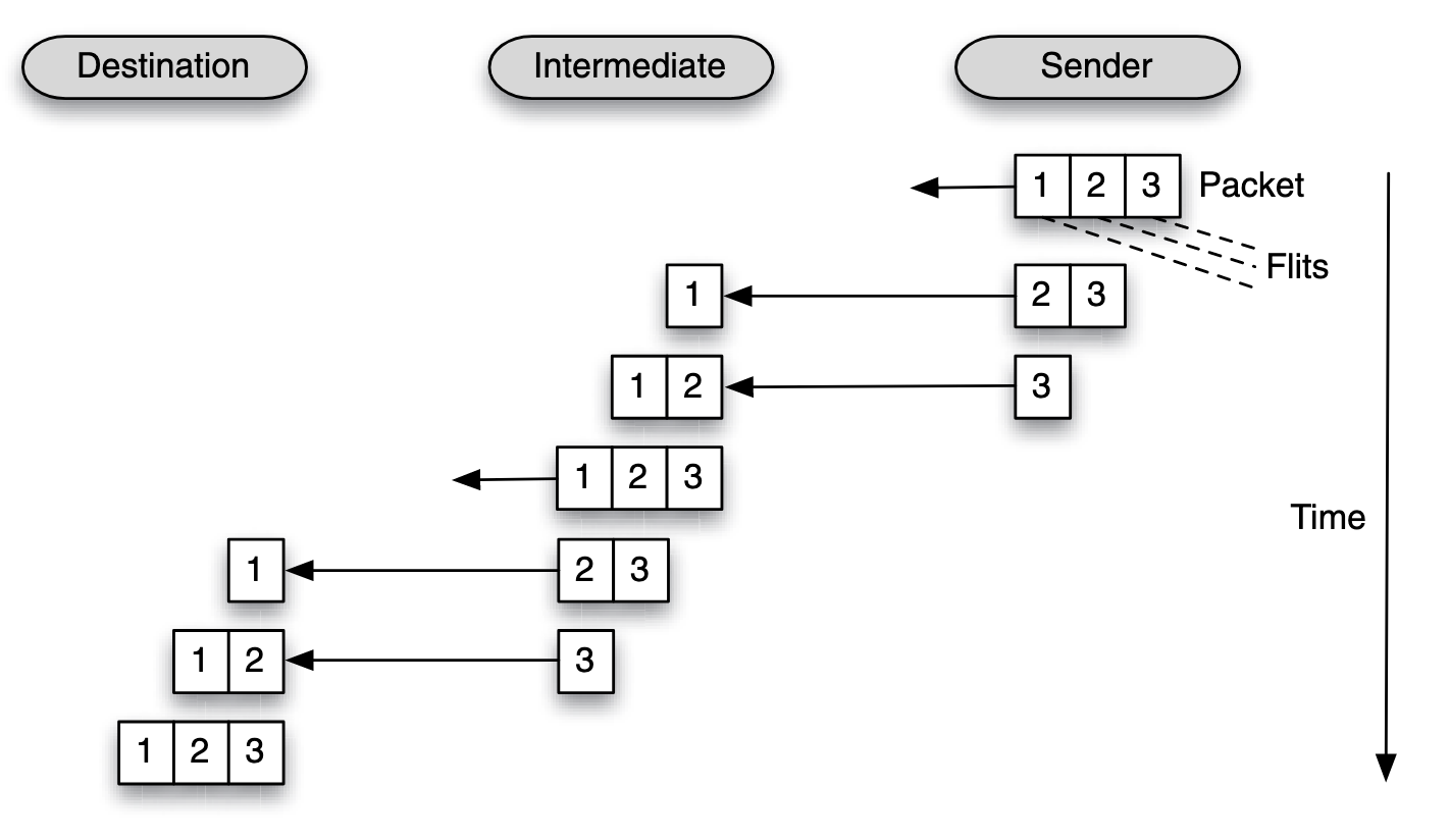
A packet must be fully received (and stored) by a node, before it can be forwarded to the next node.
Latency:
Where the first bit has to travel through hops and each hop incurs a routing latency of , then the header latency is , and the serialization latency is .
Cut-through and Wormhole
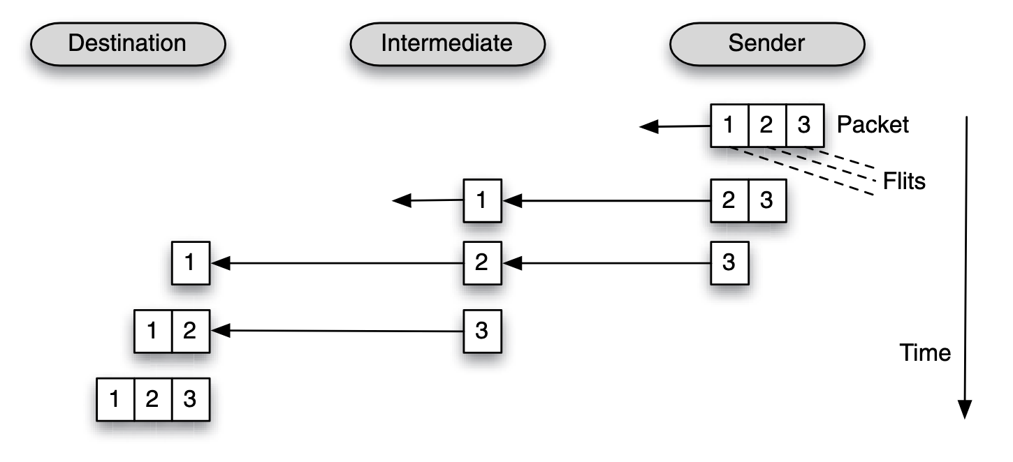
Parts of a packet can be forwarded to the next router even before the packet has fully arrived at the current router.
Latency:
Where the first bit has to travel through hops and each hop incurs a routing latency of , then the header latency is , and the serialization latency is .
Key benefit of cut-through or wormhole routing is lower packet transmission latency.
The high level view of cut-through and wormhole policy is quite the same, but they are difference when down to the granularity of their flow control unit.
- In a cut-through routing, the fow control works on a packet size granularity
- in a wormhole routing, the fow control works on a fit granularity
| Aspect | Store-and-Forward Switching | Wormhole Switching |
|---|---|---|
| Figure |  |  |
| Delivery Mechanism | Each intermediate router fully receives and stores the entire packet before forwarding. | Packets are divided into flits; only the header flit is routed, with others following immediately. |
| Latency | High, as each hop incurs the full packet transmission and processing delay. | Low, as only the header incurs routing delay, and flits flow pipeline-style. |
| Buffer Requirements | Large, as the entire packet must be buffered at each hop. | Small, as only a few flits are buffered (e.g., one or two). |
| Congestion Impact | Blocks resources until the entire packet clears, worsening congestion. | May block only portions of a packet, allowing partial progress. |
| Performance | Slower, particularly for large packets or high-diameter networks. | Faster and more efficient, especially for small flits and low-diameter networks. |
| Fault Tolerance | Can retransmit the full packet if an error occurs. | Requires retransmitting the entire packet if any flit is lost. |
Routing Algorithms
Routing options:
- Minimal: Chooses the shortest path (fewest hops).
- Non-minimal: Allows longer paths, often to bypass congestion.
- Deterministic: Always selects the same path for a given source-destination pair.
- Non-deterministic: Allows variability in path selection.
- Oblivious: Uses diverse paths, often involving randomization, without considering network state.
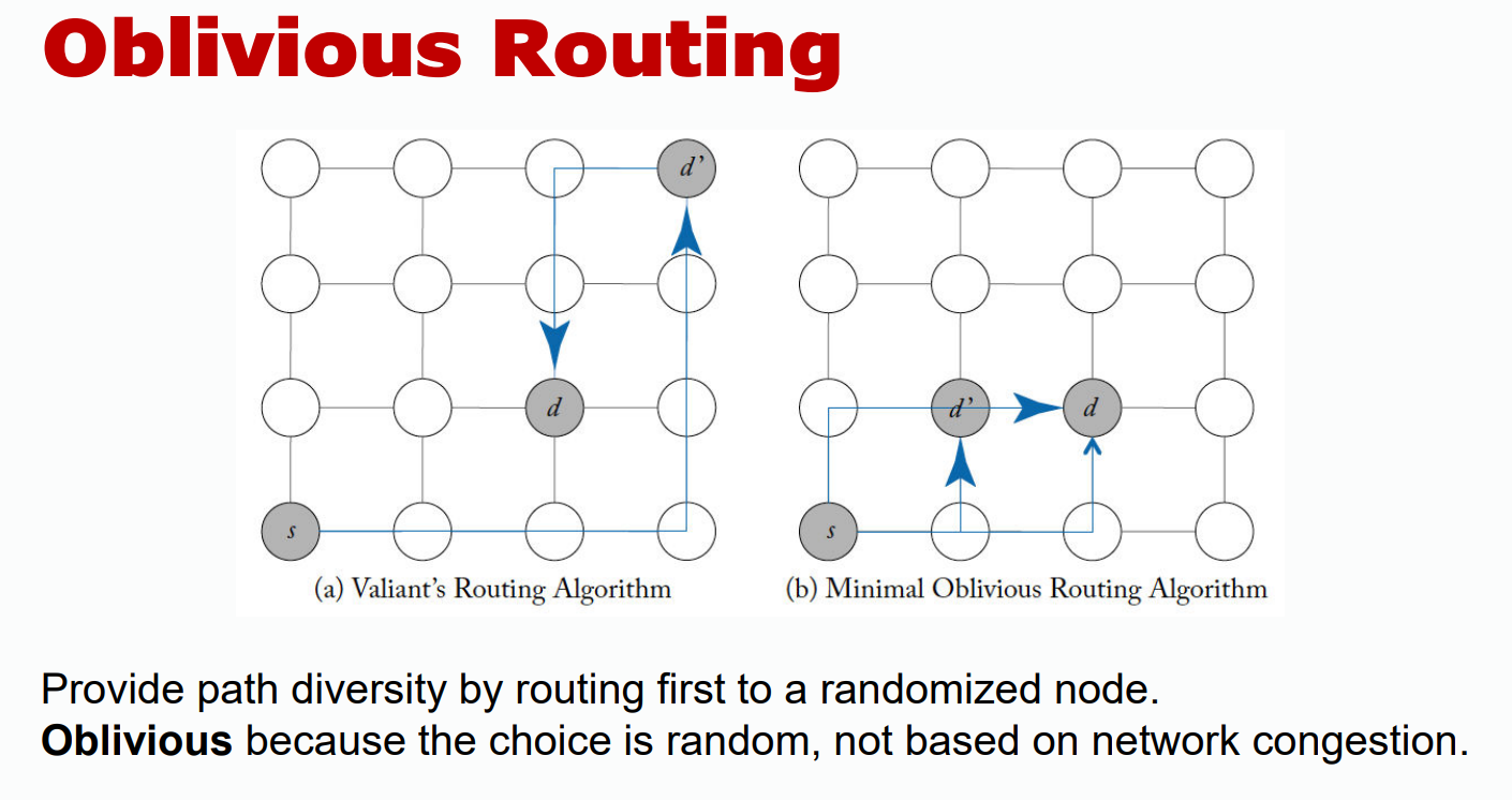
- Adaptive: Adjusts paths based on network conditions (e.g., congestion).
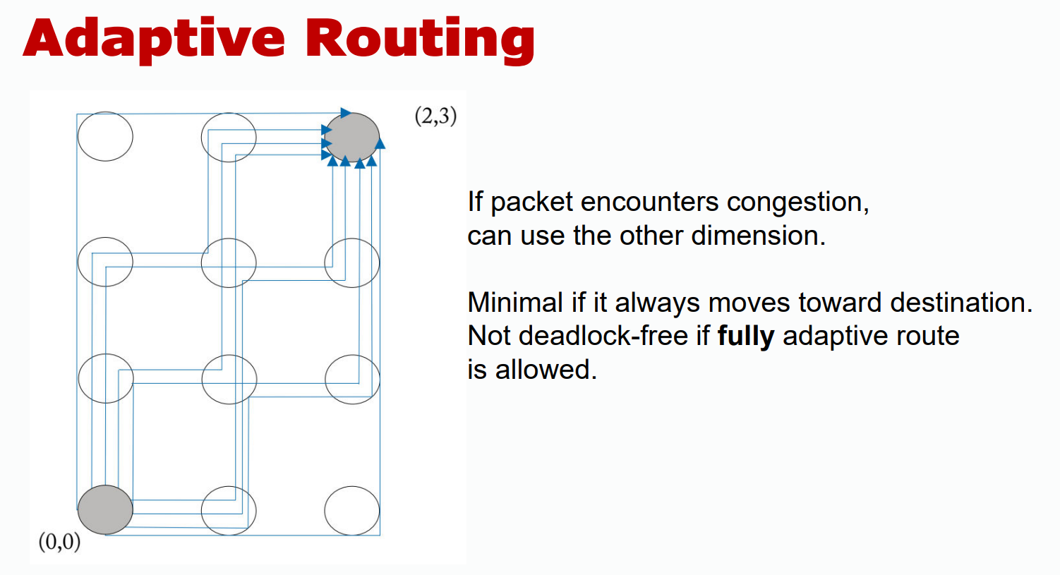
- Per-hop Routing: Each router decides the next step dynamically.
- Source Routing: The entire path is precomputed at the source.
- Deadlock-free: Ensures routing avoids deadlocks entirely.
- Dimension-ordered: Traverses dimensions (e.g., x, then y, then z) in a fixed order to simplify routing.
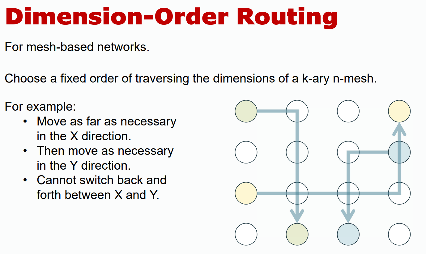
Deadlock Avoiding
Content below is not included in final exam
By Avoiding Closed Loops in Routing Path
By Restricting Allowed Turns
Router Node Implementation
Lookup Table vs. Source Routing
Router Architecture
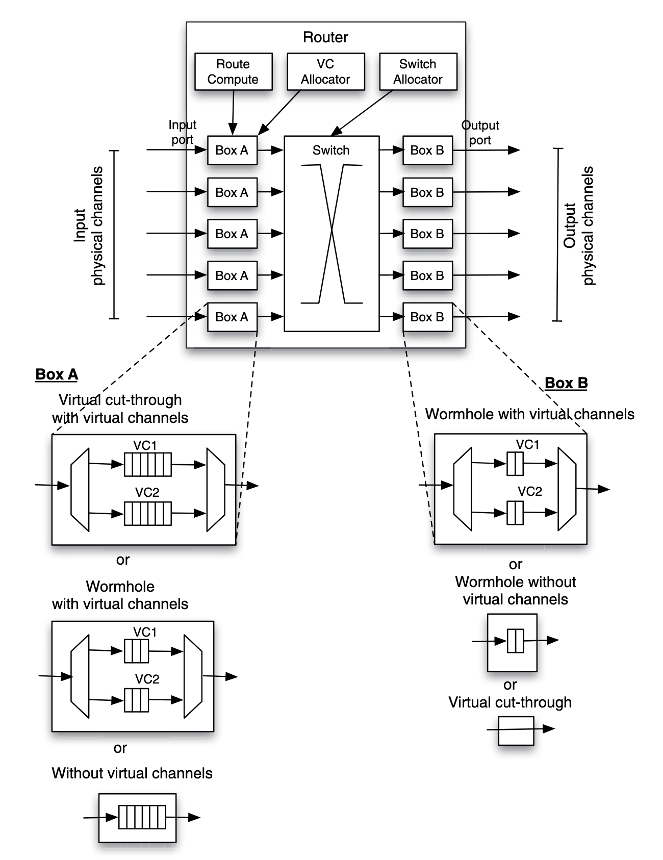
In figure, when virtual cut-through routing is used:
- on input boxes, the flow control requires the buffer to be able to accommodate an entire packet
- on output boxes, it is guaranteed that the downstream router has sufficient buffer space for an entire packet. Thus, fits of a packet can flow through directly to the output channel
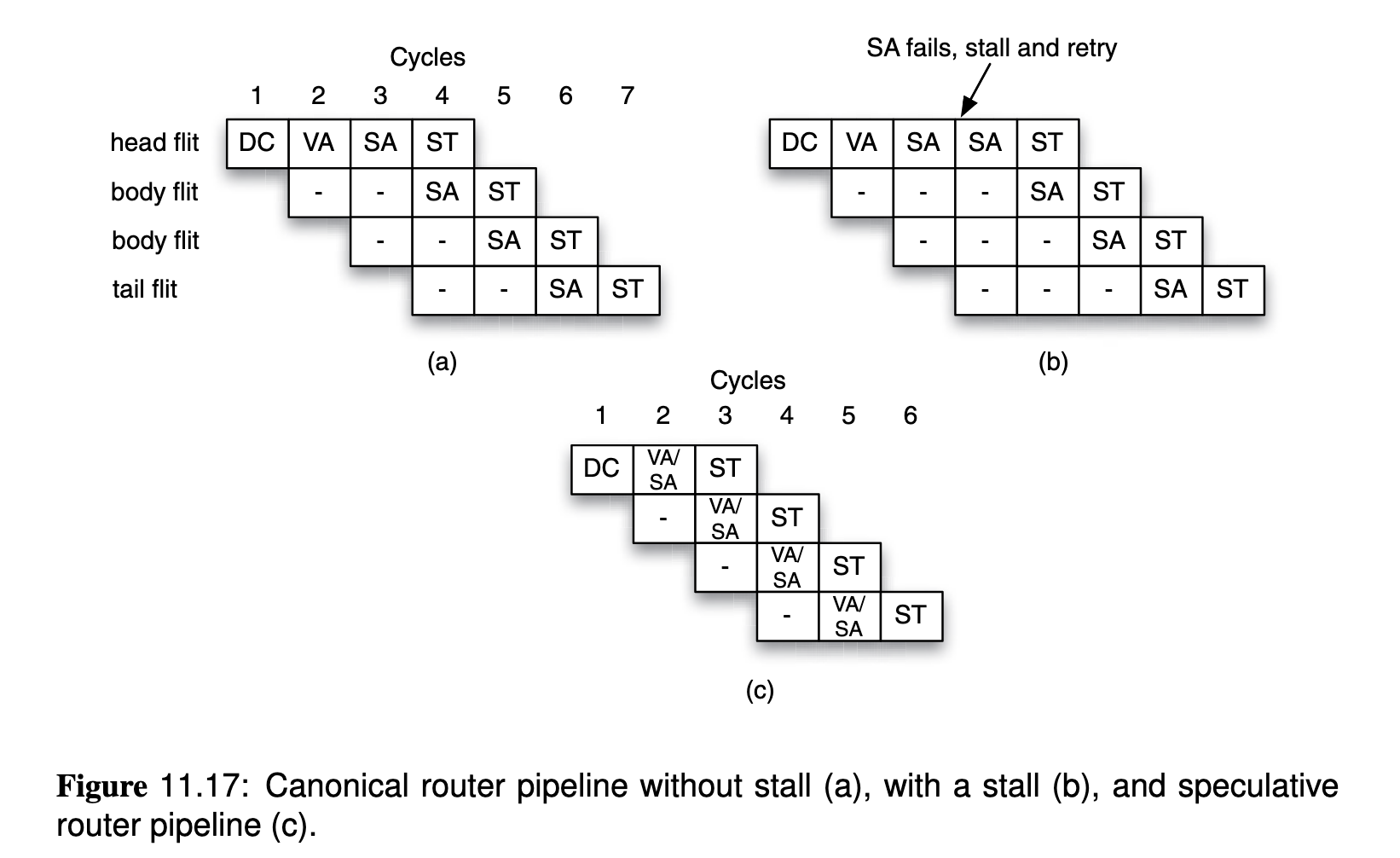
In order to send flits to the next router, header flit will be processed with:
- Decode and Compute (DC): decode header to know input channel and destination, the destination may be used to compute the output port, based on arithmetic calculation or based on a look up of the routing table.
- Virtual-Channel Allocation (VA): a request for an output virtual channel is made, and a global virtual channel arbitration decides whether the requested output virtual channel is available (can be allocated) or not.
- Switch Allocation (SA): global switch allocator allocates the switch to connect the input channel and output port (where the output virtual channel is connected).
- Switch Traversal (ST): transmit the fit is transmitted through the switch to the output virtual channel. Note that other flits of the packet(non-header) will only walk through the last two steps. Those steps are scheduled in pipelined manner:
Compared to packet switching, circuit switching can be more efficient for long distance routing.