Memory Hierarchy
Cache is the intermediate architecture that loads/stores things between CPU and main memory.
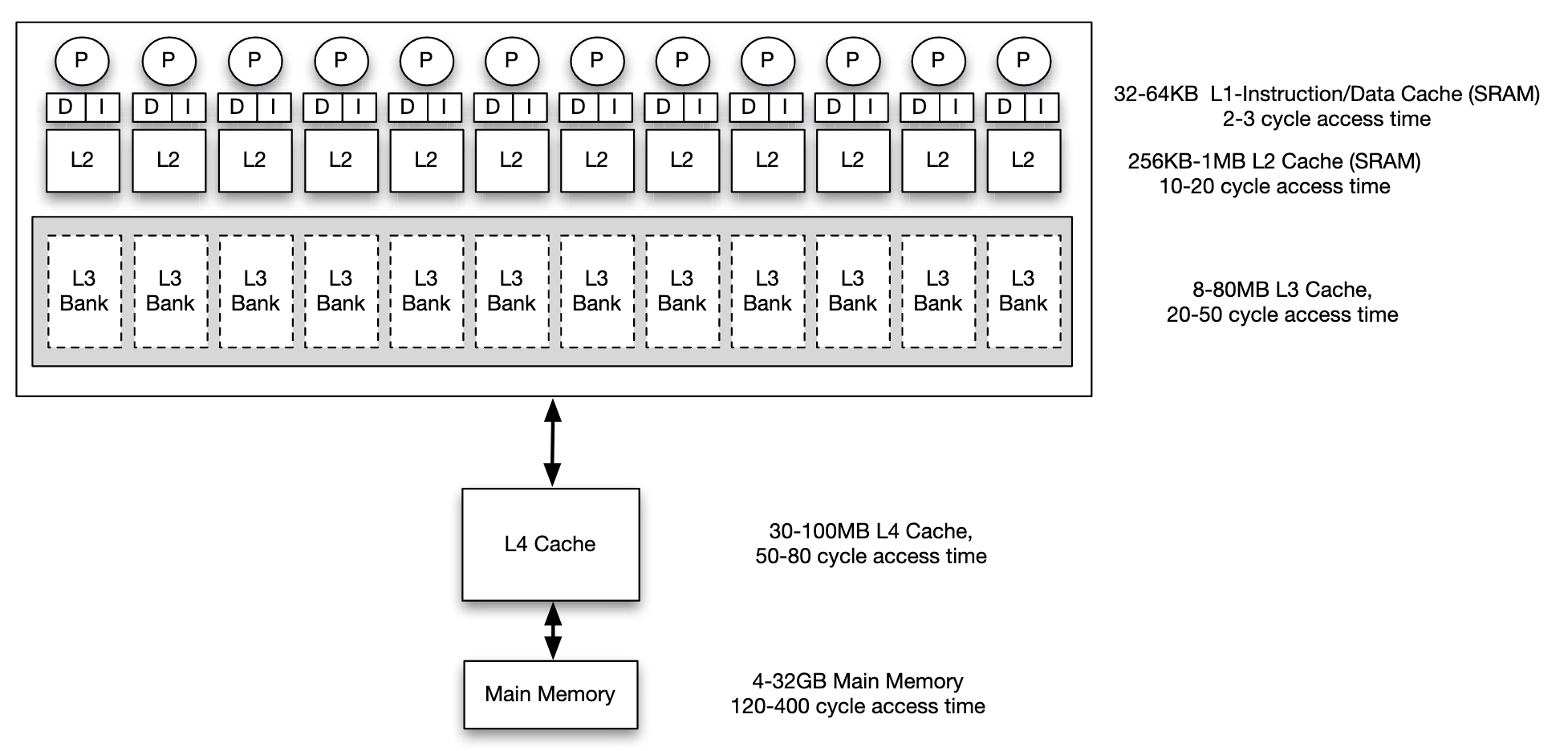 This is an example of memory hierarchy configuration in a multi core system
If CPU asks for some address not in cache, a miss occurs. There are two kinds of miss:
- Cold miss: the requested address has never been accessed(therefore never moved to cache before)
- Capacity miss: the requested address used to be in the cache but was pushed out when a different block was fetched
Cache Organization
Factors of how cache is organized: Cache Size, Associativity, Block Size.
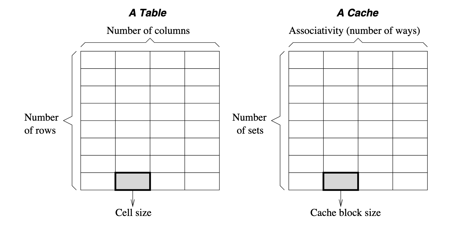
Cache Line(Cache Block) is the minimal unit to read from / write to cache(typically a fixed number of bytes, such as 64 bytes in many modern processors) Strictly speaking, they are not the same concept. Strictly cache block refers to specifically the chunk of data, while cache line refers to not only the data but also the metadata (storage location, tag, valid or dirty bits) needed for cache management.
About conflict miss Conflict miss is a type of cache miss. Conflict occurs you try to push something into a cache set when it is already full.
Since memory is much larger than memory, multiple blocks in memory will share the same position in cache, there will be conflicts and situations to deal with. Besides, the final purpose of writing to cache is to store back to memory. Therefore, main topics to care about are: Placement Policy: where to place the memory block in cache Replacement Policy: witch block to replace when new memory comes Write Policy: when to write back to memory wen cache is being written
Placement Policy
It's about where to place. Basically, address of memory can be seen as:

Concepts:
- Index Bits: Used to select which set (row) to look into.
- Tag Bits: Used to identify if the desired data block is present within the selected set.
- Block Offset: Used to locate a byte in block.
Steps to place a piece of memory into cache:
- Choose which set to place(Cache Indexing Function is used to determine the set to which block can map, it is calculated as ), blocks that map to the same set will have the same values in the index bits.
- Choose which block in the set to place. The address bits that are not part of the block offset or index bits must be stored along with the block. These bits are referred to as the tag bits.
- Select the requested byte or word if the block matches
To determine how to split an address into Tag, Index, and Block Offset bits for cache addressing, follow these steps:
- Determine the number of Block Offset bits based on the block size.
- Determine the number of Index bits based on the number of cache sets.
- Calculate the number of Tag bits by subtracting the sum of Index and Block Offset bits from the total address bits.
Given:
- Total Address Bits: 32 bits (typical for a 32-bit address space)
- Cache Size: 16 KB (16,384 bytes)
- Block Size: 64 bytes
- Associativity: 4-way set associative
Steps:
- Determine block offset bits: block size 64 bytes, access unit is byte, then bits are required
- Determine index bits:
- Given total cache size 16 KB, block size 64 bytes, there are blocks.
- Given 4 ways associativity, there is sets
- Therefore, the index takes bits
- Determine tag bits: given total address bits 32, tag bits takes bits
Understanding Ways (Columns):
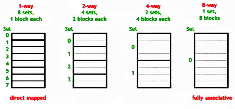
- In a set-associative cache, each set contains multiple blocks, known as ways.
- The number of ways determines how many blocks are in each set.
- Way Selection:
- The cache does not use address bits to select a way (column).
- Instead, it checks all ways in parallel by comparing the tag bits.
- The first way (if any) that matches the tag indicates a cache hit.
Therefore, to decide the format of address(that is to split the address into Tag bits, Index bits, and Block Offset bits correctly), simple steps are:
- Decide the length of
Block Offsetbits according to the given block size. - Decide the length of
Indexbits according to the given num of sets of cache. - Decide the length of
Tagbits using total bits minus block offset bits and index bits.
That means the memory is split into Tag groups(not necessarily in sequential order, depending on strategy), each of the group has Index blocks and in each block there are Block Offset bits/bytes.
[!IMPORTANT] >
Suppose a cache has a capacity of 64K bytes, and a block size of 256 bytes:
- What is the capacity within a block?
- If it is a 4-way associative cache, how many sets are there?
- For the address
0x3A074B94:
- What is the offset?
- What is the set index?
- What is the tag?
Example: Direct Mapped Cache
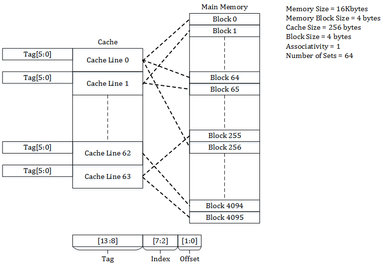 A real example:
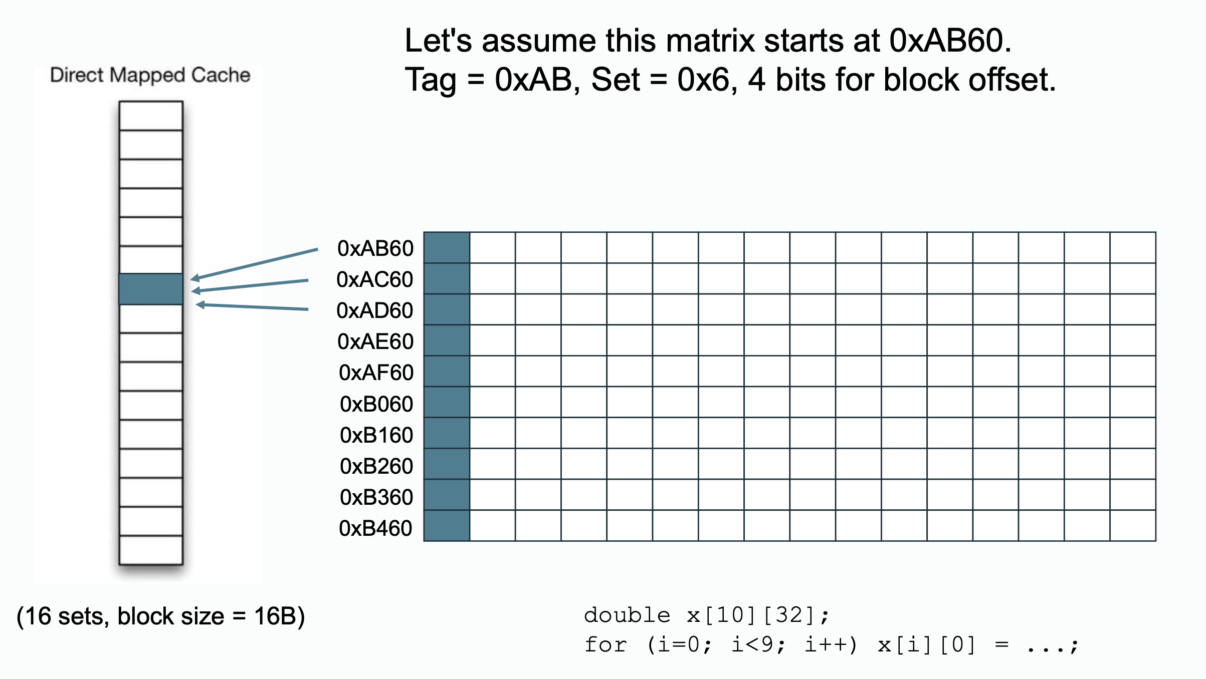 Notice that each
 double variable takes bytes in memory, there will be elements per block. In column major access pattern, they will be mapped to the same block position in cache.
One possible way to avoid things happens above is that you can append some empty elements after each line of the array so that the first element of each line won't line up to the same cache position.
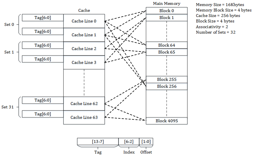
Example: Set-Associative Cache
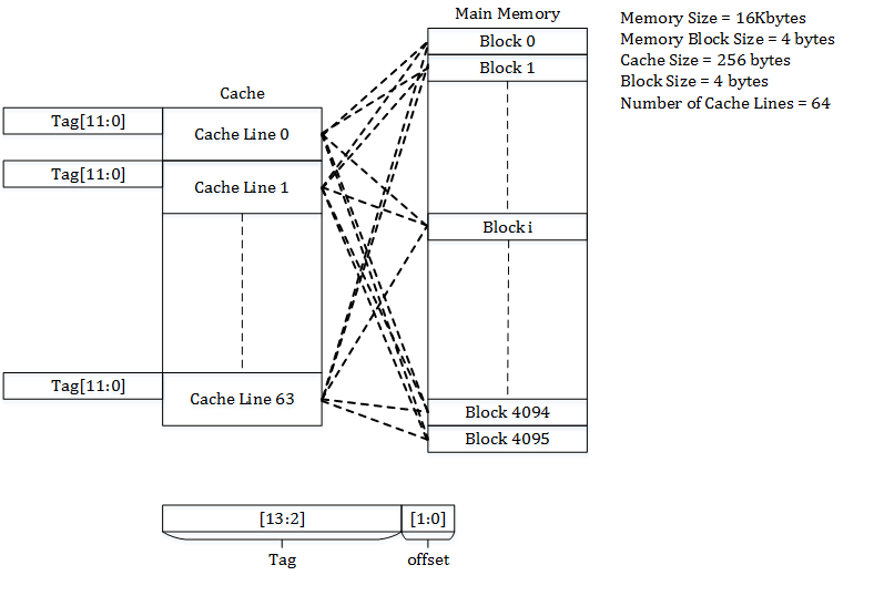
Example: Fully Associative Cache
Replacement Policy
Mainly talks about which block to replace when there are conflicts. Most popular implementation is Least Recently Used(LRU), but it incurs space overhead and becomes expensive in some situations, there are approximations like First In First Out(FIFO) policy and Most Recently Used(MRU) policy.
LRU approach via LRU matrix:
- Accessing way will sets the th row bits to and th column bits to in LRU matrix.
- Find the row with least number of 's, which is the least recent used block.
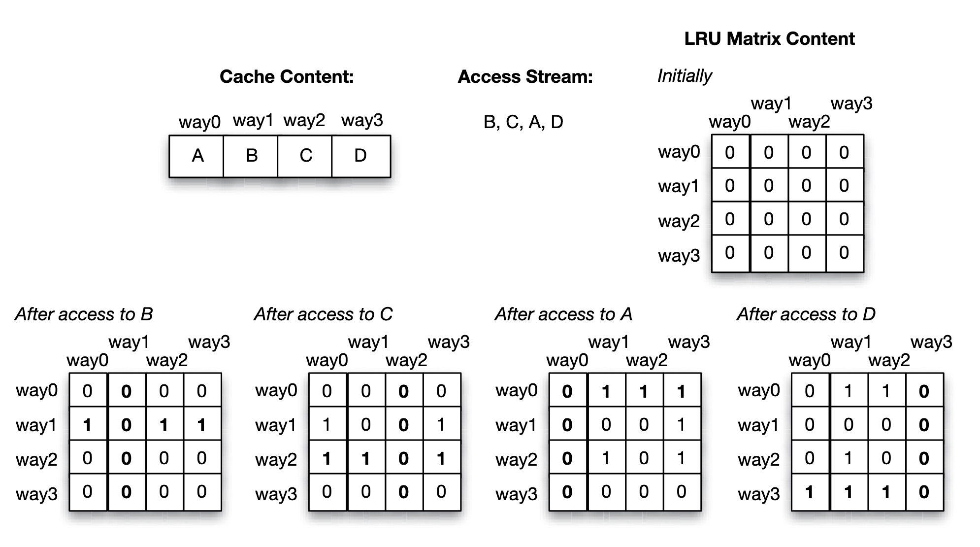
- An access to B (which resides in way 1), sets the second row bits to 1, and then the second column bits to 0.
- An access to C (which resides in way 2), sets the third row bits to 1, and then the third column bits to 0.
- An access to A (which resides in way 0), sets the first row bits to 1, and then the first column bits to 0.
- Finally, an access to D (which resides in way 3), sets the fourth row bits to 1, and then the fourth column bits to 0.
- Suppose that at this time a replacement needs to be made. By scanning the rows, we discover that way 1 (containing block B) has the least number of 1’s (it has none), hence B is the least recently used block that should be selected for eviction.
For LRU approach using LRU matrix, there is one matrix for each set of the cache, hence it is cheap to implement for small associativities but becomes expensive to implement for a highly associative cache(that is large num of ways, or large set).
Write Policy
Mainly talks about the strategy of writing cache back to the outer level memory hierarchy component(for example, L1 back to L2, or L3 back to memory). There are two choices for implementation: write through and write back policies.
- Write through policy: any bytes written by a single write event in the cache are immediately propagated to the outer level memory hierarchy component.
- Write back policy: the change is allowed to occur at the cache block without being propagated to the outer level memory hierarchy component. Only when the block is evicted, is the block “written back” or propagated, and it overwrites the stale version at the outer level.
Comparing the write through versus write back policies, the write back policy tends to conserve bandwidth usage between the cache and its outer level memory hierarchy component because there are often multiple writes to a cache block during the time the cache block resides in the cache. In the write through policy, each write propagates its value down so it consumes bandwidth on each write. As a result, the outermost level cache in a processor chip typically uses a write back policy since off-chip pin bandwidth is a limited resource. However, the choice incurs less penalty for on-chip bandwidth which tends to be much higher. For example, the L1 cache is usually backed up by an outer level L2 cache, and both of them are on-chip. The bandwidth between the L1 cache and L2 cache is quite high compared to the off-chip bandwidth.
Another aspect of the write policy is whether the block that contains the byte or word to be written needs to be brought into the cache if it is not already in the cache:
- write allocate (WA) policy: upon a write miss, the block is brought into the cache before it is written.
- Write no-allocate (WNA) policy: upon a write miss, the block is propagated down to the outer level memory hierarchy component without bringing the block into the cache.
Inclusion Policy
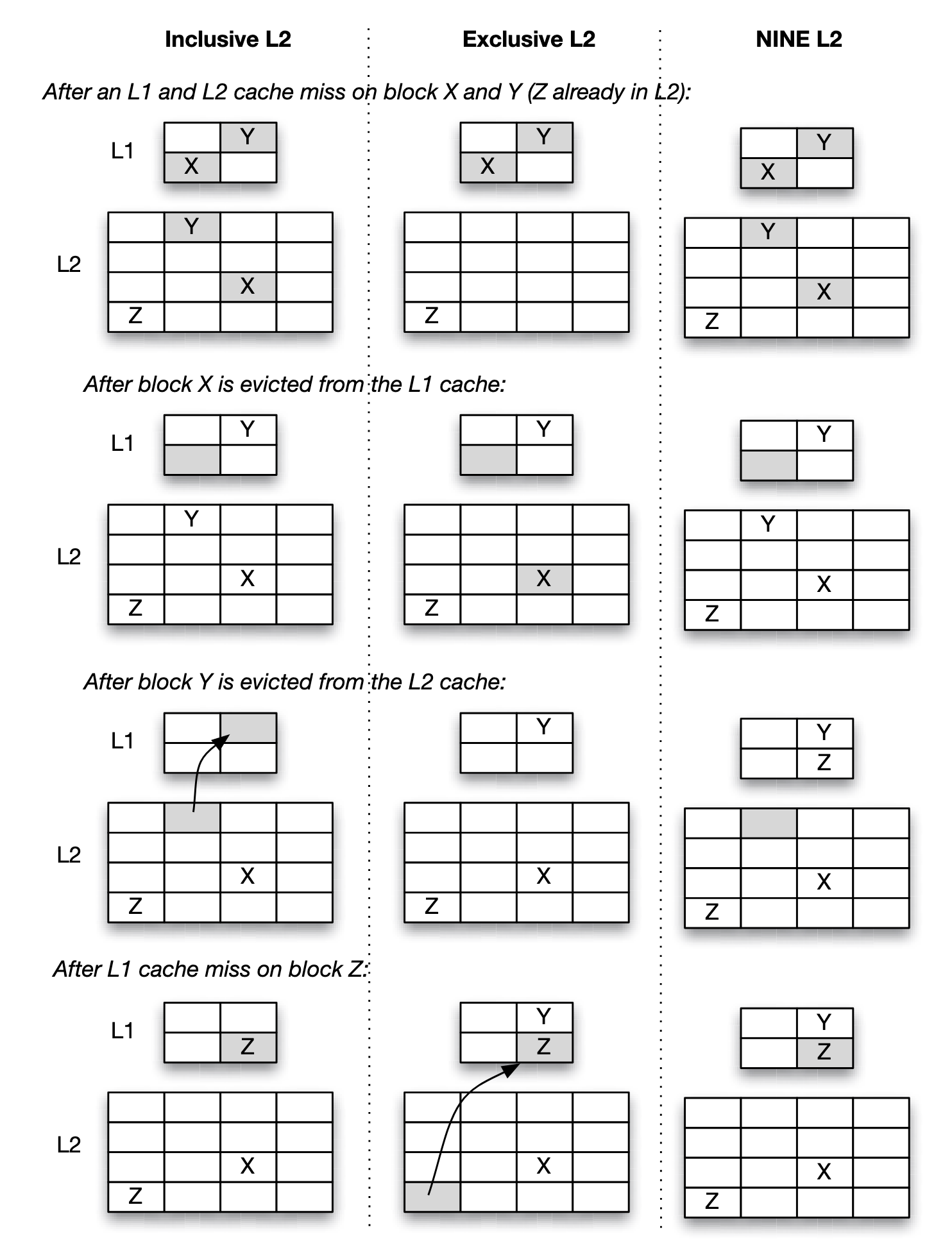
- Inclusive: Any cache line present in the L1 cache will also be present in the L2 cache.
- Exclusive: A cache line may be present in either the L1 or L2 cache, but not both.
- NINE: A cache line present in the L1 cache may or may not be present in the L2 cache.
Unified/Split/Banked Cache Organization
- Unified cache: same cache for all.
- Split cache: distinct contents can be split into different caches. For instance, the L1 cache is typically split into the instruction cache and the data cache in most processors today. Instruction fetches are issued by the fetch unit of the processor, while data fetches are issued by the load/store unit of the processor.
- Multi-banked cache: an alternative organization, rather than distinguishing types of data held in the split caches, splitting the cache over different addresses in an interleaved manner. In a multi-banked cache, multiple accesses to different banks can be performed in parallel, while accesses to the same bank result in conflict and are sequentialized.
For the most part, load/store instructions do not fetch data from the code region, unless in special cases such as self-modifying code or just-in-time compilation.
Virtual Memory, Page Table, and Translation Look aside Buffer
In a virtual memory system, a program (and its compiler) can assume that the entire address space is available for its use, even though in reality, the physical memory may be smaller than the address space viewed by the program, and it may be partitioned for simultaneous use by multiple programs.
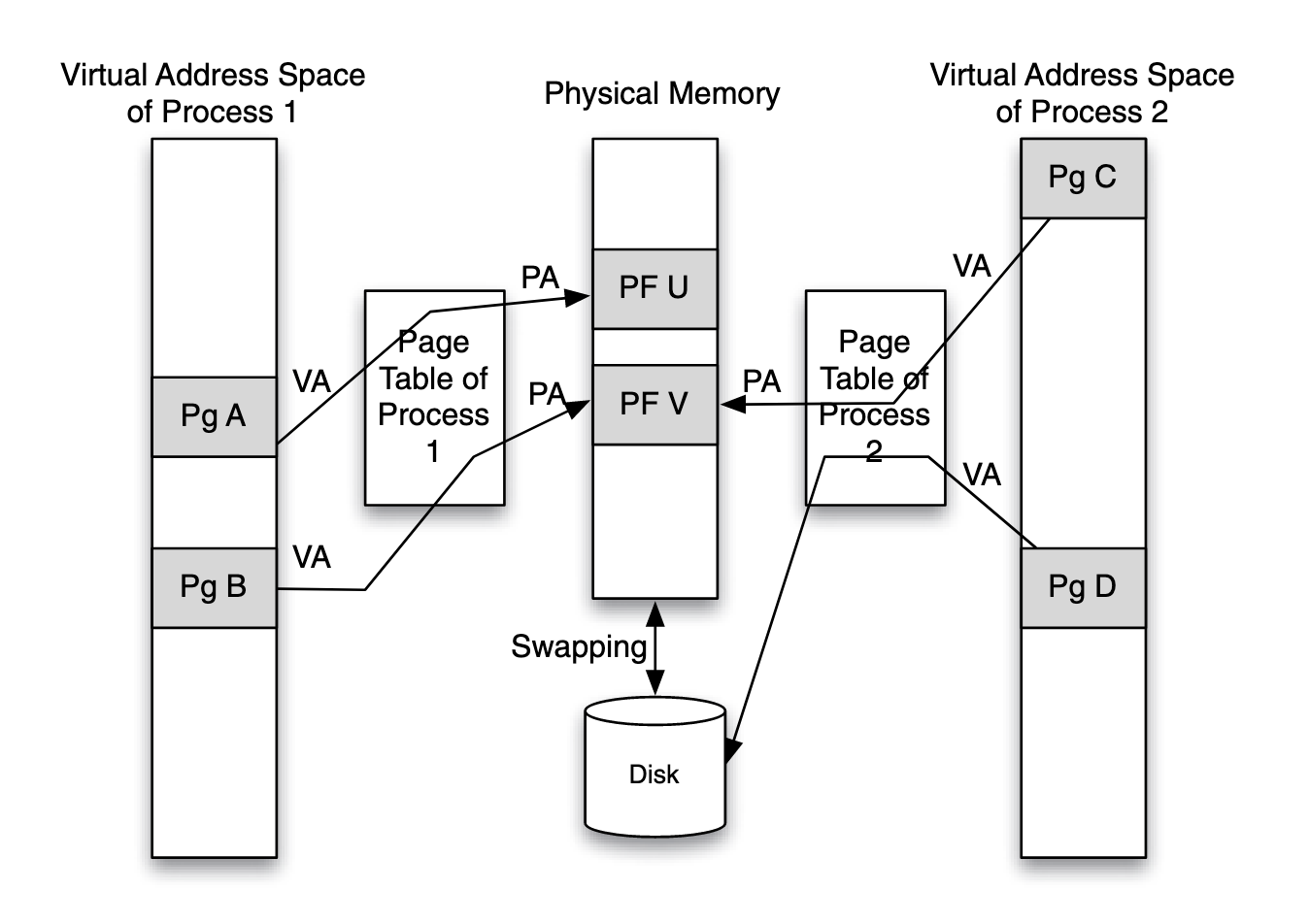
Each process’ page table maintains a mapping between the virtual address space that the process sees and the actual physical memory available in the system. The page table is a data structure that translates the virtual address (VA) of the application to the physical address (PA) in the physical memory.
The mapping between the same virtual page address (of different processes) to physical page address is different in different processes. Thus, a virtually-addressed cache cannot be shared by multiple processes
Concepts:
- The page table: a structure maintained by the OS and is stored in the main memory. In some systems, due to the huge virtual address space supported, the page table is hierarchically organized.
- The granularity of pages: the basic unit of how OS manages VA to PA mapping, typically 4KB)
- The translation look aside buffer: a cache that stores most recently used page table entries for reducing the access time. For requiring page table access for each memory access (a load or store instruction) to get the physical address to supply to the cache will cause the cache access time to be very high.
Translation Lookaside Buffer is mostly the same as cache on structure, but there are subtle differences. For example, 16 entries in the TLB cover 16 × 4 = 64KB of memory, which is as much memory as covered by a large L1 data cache. Thus, a TLB can get by with fewer entries compared to the L1 cache or L2 cache.
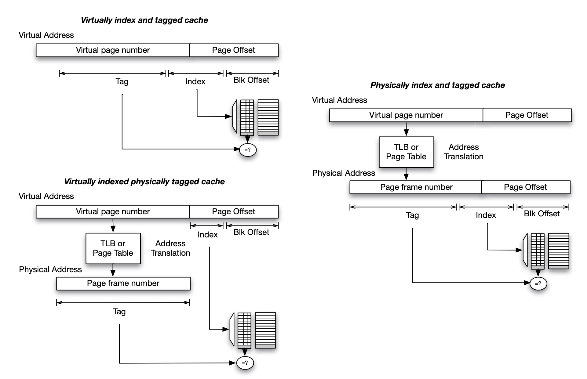
- Virtual addressing (top left): index the cache using the index bits from virtual address, and store tag bits of the virtual address in the cache's tag array
- Physical addressing(right): index the cache using index bits of the physical address, and store tag bits of the physical address in the cache's tag array
- Virtual indexing and physical tagging: block offset bits are shared and valid for both physical address and virtual address.
Non-Blocking Cache
A high-performance processor may generate memory accesses even as an earlier memory access already suffers from a cache miss. In early cache designs, these memory accesses will stall until the access that misses in the cache is satisfied. This can obviously hurt performance. Modern cache architectures overcome this limitation by introducing a structure referred to as miss status handling registers (MSHRs). When a cache access suffers a cache miss, an MSHR is allocated for it to keep track of the status of the miss
Cache Misses
Cache performance is measured by cache hits versus cache miss. There are different types of cache misses:
- Compulsory misses (also refer to cold misses): the target memory block is being requested for the first time, and it has never been loaded into cache before.
- Conflict misses: multiple blocks of data compete for the same cache location, even though there is unused space elsewhere in the cache.
- Capacity misses: the cache is too small to hold all the data required by the program during its execution.
- Coherence miss: misses that occur due to the need to keep the cache coherent in shared memory multiprocessor systems.
- System related misses: when a process is suspended due to an interrupt, system call, or context switch, the new running thread loads different memory which perturbs current cache state, when the process resumes execution, it will suffer from new cache misses restoring cache state that has been perturbed.
Clod misses are measured by the number of times new blocks are fetched into the cache, therefore they are affected by the cache block size.
How cache parameters affect the different types of misses:
| Parameter | Cold | Conflict | Capacity | Coherence |
|---|---|---|---|---|
| cache size | - | - | not directly related | |
| block size | / | / | not directly related | |
| associativity | - | - | not directly related |
Increasing block size, the num of variables that can be stored in one cache block is increased, thus one load will cause more variable being in cache, which reduces cold miss in programs with locality.
Intuitively, increasing the cache size reduces the number of capacity misses, while increasing cache associativity reduces the number of conflict misses. However, capacity misses and conflict misses are sometimes intermingled. Increasing the cache size while keeping cache associativity constant (hence increasing the number of sets) changes the way blocks in memory map to sets in the cache. Such a change in mapping often influences the number of conflict misses, either increasing or decreasing it
Power law is proposed to estimate miss rate for specific cache size, based on empirical observation:
- is a measure of how sensitive the workload is to change in cache size
- is the miss rate of a workload for a baseline cache size
- is the miss rate for a new cache size
There are situations in which the power law does not fit(for power law is good at represent average behavior of a group of applications). Stack Distance Profile is an improved representation of the behavior of individual applications.
- -way associativity cache with LRU replacement policy
- are counters maintained by LRU, if it is a cache access in position , then is incremented. If it is a cache miss, the block is not found in the LRU stack, resulting in incrementing the miss counter
- Hence is miss rate for a smaller cache that has associativity, where
Cache Performance Matrix
Average Access Time (AAT) is one of the meaningful metrics to evaluate cache performance. For a system with levels of caches:
- denote the access time of the cache and memory.
- are the cache miss rates of the and cache
However, ATT does not correspond directly to execution time, which is the ultimate measure of performance.
To measure overall program performance, cycles per Instruction (CPI) can be considered.
- is CPI for ideal memory hierarchy, in which cache never suffers from miss and has access latency.
- is the fraction of instructions that reference memory.
- is average access time we talked about above.